LOGICAL INSTRUCTION
instructions, which are used to perform operations such as AND, OR, Compare, Rotate etc.
| Opcode | Operand | Description |
|---|---|---|
| CMP | R M |
Compare register or memory with accumulator |
| CPI | 8-bit data | Compare immediate with accumulator |
| ANA | R M |
Logical AND register or memory with accumulator |
| ANI | 8-bit data | Logical AND immediate with accumulator |
| ORA | R M |
Logical OR register or memory with accumulator |
| ORI | 8-bit data | Logical OR immediate with accumulator |
| XRA | R M |
Logical XOR register or memory with accumulator |
| XRI | 8-bit data | XOR immediate with accumulator |
| RLC | None | Rotate accumulator left |
| RRC | None | Rotate accumulator right |
| RAL | None | Rotate accumulator left through carry |
| RAR | None | Rotate accumulator right through carry |
| CMA | None | Complement accumulator |
| CMC | None | Complement carry |
| STC | None | Set carry |
1) CMP instruction:
The contents of the given register or addressed memory location are compared with the accumulator contents. In fact the contents of the register or addressed memory location are subtracted from the contents of accumulator and the accumulator contents remain unchanged. However, as a result of the subtraction the flags are modified as per the result. The possible combinations of this instruction are as given below:
CMP reg (Compare Register)
CMP M (Compare Memory)
The result of the comparison is shown by setting the flags as follows:
if (A) < (reg/mem): carry flag(CY = 1) is set
if (A) = (reg/mem): zero flag(Z = 1) is set
if (A) > (reg/mem): carry(CY = 0) and zero(Z = 0) flags are reset.
| Operand | Bytes | Flags Affected | M-Cycles | T-States |
|---|---|---|---|---|
| Register | 1 | All | 1 | 4 |
| Memory | 1 | All | 2 | 7 |
2) CPI instruction:
It is similar to CMP instruction with the difference that the 8-bit data is directly given with the instruction. In this instruction the given data is compared with the accumulator contents. The flags will be modified as per the result.
| Operand | Bytes | Flags Affected | M-Cycles | T-States |
|---|---|---|---|---|
| 8-bit data | 2 | All | 2 | 7 |
3) ANA instruction:
In this instruction each bit of the given register or memory location addressed by H-L register pair contents are ANDed with each bit of the accumulator contents (bit by bit). The result is saved in the accumulator. It does not affect the contents of the given register.
The ANA reg/M instruction clears (resets) the CY flag and all other flags are modified according to the data conditions of the result. This instruction is one byte instruction. The possible combinations of this instruction are as given below:
ANA reg (AND Register)
ANA M (AND Memory)
For example A = 73 H, C = C3 H, CY = 1,
ANA C
after the execution of the instruction ANA C we get the CY = 0,A = 43 H.
| Operand | Bytes | Flags Affected | M-Cycles | T-States |
|---|---|---|---|---|
| Register | 1 | All,CY=0,AC=1 | 1 | 4 |
| Memory | 1 | All,CY=0,AC=1 | 2 | 7 |
4) ANI instruction:
In this instruction each bit of the given 8-bit data is immediately ANDed with each bit of the accumulator contents (bit by bit). The result is stored in the accumulator. The difference between ANA reg and ANI data instruction is that in ANA reg the data given in the register where as in the ANI data instruction, the data is given with the instruction itself.
For example, if A = AB H and CY = 1,
ANI 06H
after the execution of the instruction ANI 06 H we get the CY = 0,A = 02 H.
| Operand | Bytes | Flags Affected | M-Cycles | T-States |
|---|---|---|---|---|
| 8-bit data | 2 | All,CY=0,AC=1 | 2 | 7 |
5) ORA instruction:
In this instruction each bit of the given register or memory location addressed by H-L register pair contents are ORed with each bit of the accumulator contents (bit by bit). The result is saved in the accumulator. It does not affect the contents of the given register.
The ORA reg/M instruction clears (resets) the CY flag and all other flags are modified according to the data conditions of the result. This instruction is one byte instruction. The possible combinations of this instruction are as given below:
ORA reg (OR Register)
ORA M (OR Memory)
For example A = 73 H, C = C3 H, CY = 1,
ORA C
after the execution of the instruction ORA C we get the CY = 0,A = F3 H.
| Operand | Bytes | Flags Affected | M-Cycles | T-States |
|---|---|---|---|---|
| Register | 1 | All,CY=0,AC=0 | 1 | 4 |
| Memory | 1 | All,CY=0,AC=0 | 2 | 7 |
6) ORI instruction:
In this instruction each bit of the given 8-bit data is immediately ORed with each bit of the accumulator contents (bit by bit). The result is stored in the accumulator. The carry flag will be reset after the execution of this instruction and other flags will be affected as per the result.
For example A = AB H, CY = 1,
ORI 16H
after the execution of the instruction ORI 16H we get the CY = 0,A = BF H.
| Operand | Bytes | Flags Affected | M-Cycles | T-States |
|---|---|---|---|---|
| 8-bit data | 2 | All,CY=0,AC=0 | 2 | 7 |
7) XRA instruction:
In this instruction each bit of the given register or memory location addressed by H-L register pair contents are XORed with each bit of the accumulator contents (bit by bit). The result is saved in the accumulator. It does not affect the contents of the given register.
The XRA reg/M instruction clears (resets) the CY flag and all other flags are modified according to the data conditions of the result. This instruction is one byte instruction. The possible combinations of this instruction are as given below:
XRA reg (Exclusive OR Register)
XRA M (Exclusive OR Memory)
For example A = 19 H, H = 22 H, L = 00 H, M2200 = 37 H and CY = 1,
XRA M
after the execution of the instruction XRA M we get the CY = 0,A = 2E H.
| Operand | Bytes | Flags Affected | M-Cycles | T-States |
|---|---|---|---|---|
| Register | 1 | All,CY=0,AC=0 | 1 | 4 |
| Memory | 1 | All,CY=0,AC=0 | 2 | 7 |
8) XRI instruction:
In this instruction each bit of the given 8-bit data is immediately XORed with each bit of the accumulator contents (bit by bit). The result is stored in the accumulator. The carry flag will be reset after the execution of this instruction and other flags will be affected as per the result.
For example A = AB H, CY = 1,
XRI 12H
after the execution of the instruction XRI 12H we get the CY = 0,A = B9 H.
| Operand | Bytes | Flags Affected | M-Cycles | T-States |
|---|---|---|---|---|
| 8-bit data | 2 | All,CY=0,AC=0 | 2 | 7 |
9) RLC instruction:
This is mnemonic for Rotate Accumulator Left.In this instruction, the bits of the accumulator contents are shifted or rotated left. The LSB of the accumulator is changed as MSB (before the execution). The CY flag is modified as MSB (before the execution).
[An+1] < - [An] , [A0] < - [A7] also [CY] < - [A7]
| Operand | Bytes | Flags Affected | M-Cycles | T-States |
|---|---|---|---|---|
| None | 1 | Only CY | 1 | 4 |
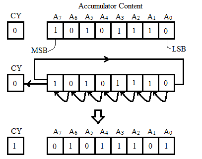
For example A = AE H, CY = 0,
RLC
after the execution of the instruction RLC we get the A = 5D H, CY = 1.
MSB is saved in CY flag and also in the LSB of the accumulator. The other bits are shifted left as shown in figure

10) RRC instruction:
This is mnemonic for Rotate Accumulator Right.In this instruction, all the bits of accumulator are shifted or rotated right. The MSB of the accumulator is changed as LSB (before the execution). The CY flag is modified as LSB (before the execution).
| Operand | Bytes | Flags Affected | M-Cycles | T-States |
|---|---|---|---|---|
| None | 1 | Only CY | 1 | 4 |
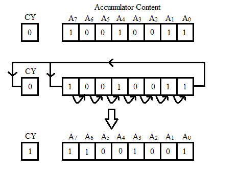
For example A = 93 H, CY = 0,
RRC
after the execution of the instruction RRC we get the A = C9 H, CY = 1.
LSB is saved in CY flag and also in the MSB of the accumulator. The other bits are shifted left as shown in figure

11) RAL instruction:
This is mnemonic for Rotate Accumulator Left Through Carry.In this instruction, the bits of the accumulator contents will be shifted / rotated left through carry. The content of carry flag CY will be stored in LSB of the accumulator and MSB of the accumulator will be stored in CY flag. All other bits of the accumulator will be shifted to the left.
| Operand | Bytes | Flags Affected | M-Cycles | T-States |
|---|---|---|---|---|
| None | 1 | Only CY | 1 | 4 |
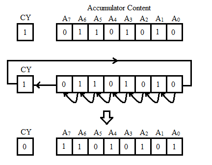
For example A = 6A H, CY = 1,
RAL
after the execution of the instruction RAL we get the A = D5 H, CY = 0.
the accumulator contents will be shifted as shown in figure

12) RAR instruction:
This is mnemonic for Rotate Accumulator Right Through Carry.In this rotate instruction, all the bits of the accumulator contents will be shifted / rotated right through carry. The content of carry flag CY will be stored in MSB of the accumulator and LSB of the accumulator will be stored in CY flag; and all other bits of the accumulator will be shifted to the right.
| Operand | Bytes | Flags Affected | M-Cycles | T-States |
|---|---|---|---|---|
| None | 1 | Only CY | 1 | 4 |
For example A = 76 H, CY = 1,
RAR
after the execution of the instruction RAR we get the A = BB H, CY = 0.
the accumulator contents will be shifted as shown in figure

13) CMA instruction:
This is mnemonic for Complement Accumulator.This is one byte implied addressing instruction as no operand is required with the instruction. The execution of this instruction inverts each bit of the accumulator contents and the result is saved in the accumulator. Basically it produces 1’s complement of the accumulator contents. No flag is affected with this instruction.
[A] < - [A∁]
For example, if A = 0B H,
CMA
after the execution of the instruction CMA we get the A = F4 H.
| Operand | Bytes | Flags Affected | M-Cycles | T-States |
|---|---|---|---|---|
| None | 1 | None | 1 | 4 |
14) CMC instruction:
This is mnemonic for Complement the carry.This instruction complements the carry flag.
If CY = 1 before the execution of CMC instruction, the carry flag will be reset (CY = 0) after the execution of this instruction. Similarly, If CY = 0 before the execution of CMC instruction, the carry flag will be set (CY = 1) after the execution of this instruction.In this only carry flag will be affected and all other flags will not be affected.
[CY] < - [CY∁]
| Operand | Bytes | Flags Affected | M-Cycles | T-States |
|---|---|---|---|---|
| None | 1 | Only CY | 1 | 4 |
15) STC instruction:
This is mnemonic for Set the carry.It sets the carry flag.
The carry flag will be set (CY = 1) irrespective of the carry flag is set or reset before the execution of this instruction STC.Only carry flag gets affected with this instruction.
[CY] < - [1].
| Operand | Bytes | Flags Affected | M-Cycles | T-States |
|---|---|---|---|---|
| None | 1 | Only CY | 1 | 4 |