CONTROL INSTRUCTIONS
instructions, which are used to for control the operation of microprocessor.
| Opcode | Operand | Description |
|---|---|---|
| NOP | None | No operation |
| HLT | None | Halt |
| DI | None | Disable interrupt |
| EI | None | Enable interrupt |
| SIM | None | Set Interrupt Mask |
| RIM | None | Read Interrupt Mask |
1) NOP instruction:
This is mnemonic for No Operation.This instruction does not do anything.It occupies only 1 byte in memory. It is useful for generating small-time delays.NOP instruction uses up about 1.3 micro-seconds for the instruction fetch and execution.
NOP instruction is very useful when we are required to delete or insert a few instruction in our program. For example we have long program as shown,
Memory Contents
address
A400H LDA 2100H
A403H MOV E,A
A404H MOV D,A
A405H MOV B,A
.
.
B800H HLT
After debugging we come to the conclusion that the instruction MOV D,A at location A404H should be removed.we just have to replace 'MOV D,A' with NOP instruction. There is no need for moving up by one position the program portion from A404H to B800H.
| Operand | Bytes | Flags Affected | M-Cycles | T-States |
|---|---|---|---|---|
| None | 1 | None | 1 | 4 |
2) HLT instruction:
HLT instruction is also not memory reference instruction, as it is complete itself and no operand is used with this instruction. HLT instruction stops further processing of the computer. This instruction must be used as the last instruction of every program otherwise meaningless answer will be obtained.As shown in above example.
| Operand | Bytes | Flags Affected | M-Cycles | T-States |
|---|---|---|---|---|
| None | 1 | None | 2 | 5 |
3) DI instruction:
This is mnemonic for Disable Interrupts. This instruction DI stands for Disable Interrupts. When this instruction is executed, it produces a high DI bit and results a low IE (interrupt enable flag) signal. The low IE signal disables all the interrupts except TRAP.
| Operand | Bytes | Flags Affected | M-Cycles | T-States |
|---|---|---|---|---|
| None | 1 | None | 1 | 4 |
4) EI instruction:
This is mnemonic for Enable Interrupts. This instruction EI stands for Enable Interrupt. When this instruction is executed, it produces a high EI signal produces a high signal to interrupt enable flag (IE). This way EI instruction enables all the interrupts except TRAP.
| Operand | Bytes | Flags Affected | M-Cycles | T-States |
|---|---|---|---|---|
| None | 1 | None | 1 | 4 |
5) SIM instruction:
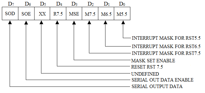
It stands for set Interrupt Mask.This instruction is used by loading the accumulator as shown in figure. The accumulator is loaded by MVI A, data (data bits are as per the requirements) instruction. The SIM instruction is then executed.

The meanings of the different bits for SIM are given below:
- The bits D0 to D2 are the mask bits (M 5.5 to M 7.5). A high to either of these bits represents that the particular interrupt is masked and a low, however, to either of these bits represents the enabling of that particular interrupt.
- The bit D3 is known as MSE (Mask Set Enable). When this bit is low, the mask bits D0 to D2 are ignored. A high to this bit indicates that the bits D0 to D2 are valid as described above.
- The bit D4 when high to override RST 7.5.
- D5 is undefined bit.
- The bits D6 to D7 are used for the serial transfer of data through the SOD line. The working of these pins will be described later.
Let us take an example to illustrate the function of SIM instruction. For example we have
MVI A,0CH
SIM
The SIM instruction after its execution will enable MSE signal (as D3 bit is high). RST 7.5 interrupt is masked (bit D2 is 1) and RST 5.5 and RST 6.5 interrupts are unmasked (enabled) as bits D0 and D1 are both 0. It will prevent the RST 7.5 interrupt from arriving at the final output.
D7 = 0 ,D6 = 0 ,D5 = 0 ,D4 = 0 ,D3 = 1 ,D2 = 1 ,D1 = 0 ,D0 = 0 .
| Operand | Bytes | Flags Affected | M-Cycles | T-States |
|---|---|---|---|---|
| None | 1 | None | 1 | 4 |
6) RIM instruction:
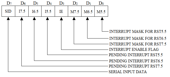
It stands for Read Interrupt Mask. This instruction will give the present status of the interrupt. This instruction loads the accumulator with 8 bit data whose details are as shown in figure

The meanings of the different bits for RIM are given below:
- The bits D0 to D2 represent the masking of RST 5.5, RST 6.5 and RST 7.5 interrupts. A high to either of these bits represents that the particular interrupt is enabled; and a low to either of these bits represents that the particular interrupt is disabled.
- The bit D3 is known as interrupt enable flag (IE). When this bit is low, all the interrupts except TRAP are disabled and a high to this bit mask the bits D0 to D2 are ignored. A high to this bit indicates that the bits D0 to D2 are valid as described above.
- The bits D4 to D6 represent the pending interrupts. A high to either of these bits represents that particular interrupt is pending; and a low to either of these bits represents that particular interrupt is not pending.
- The bit D7 is a serial input data and used for the serial input data through SID line. The working of this bit will be discussed later.
| Operand | Bytes | Flags Affected | M-Cycles | T-States |
|---|---|---|---|---|
| None | 1 | None | 1 | 4 |